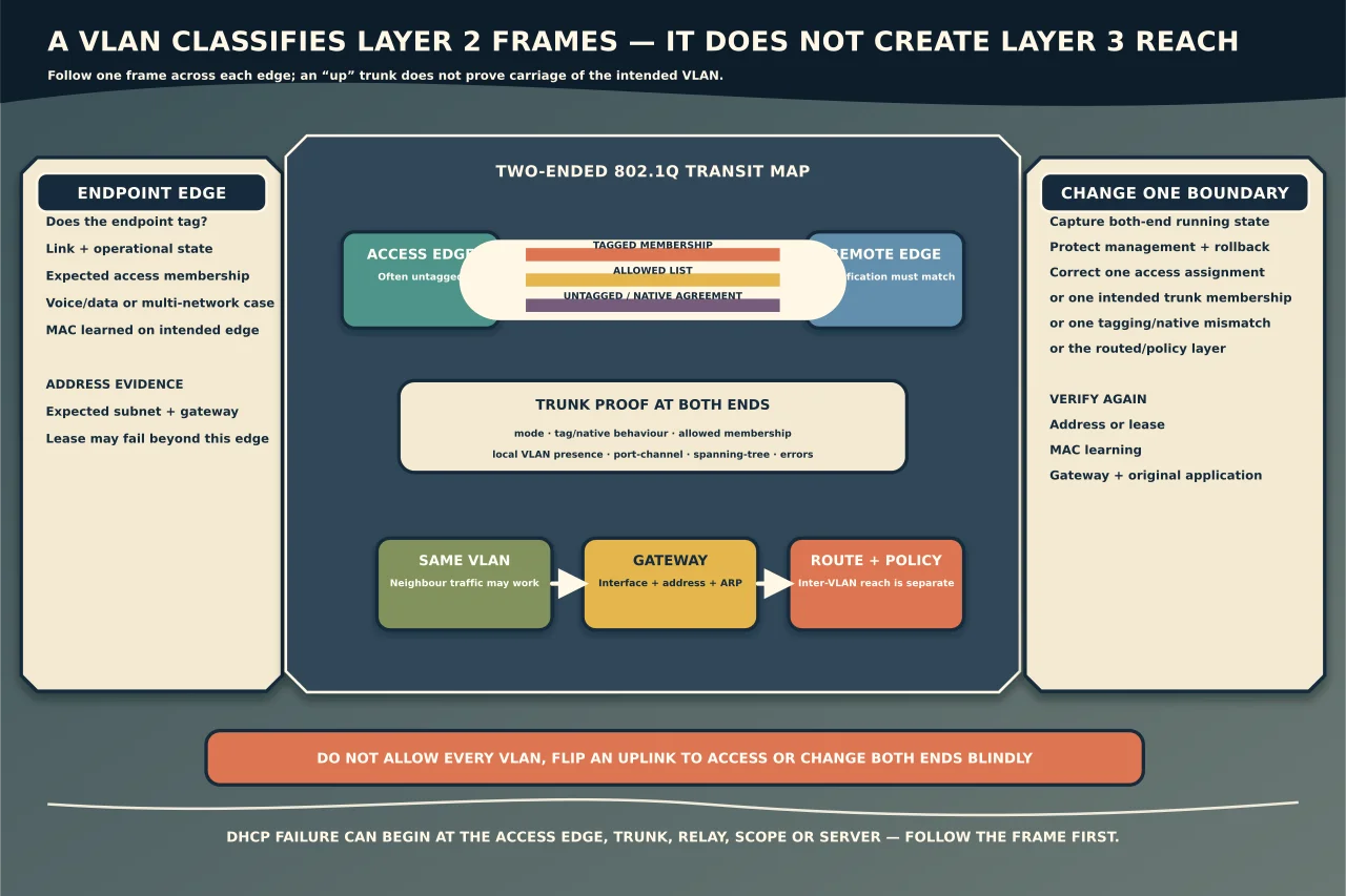
A VLAN creates a separate Layer 2 broadcast domain on switching infrastructure. It does not, by itself, create an IP subnet, firewall rule or internet connection—although designs commonly map one subnet and gateway to each VLAN.
Access ports and trunks solve different edges
An access port normally connects an ordinary endpoint to one configured VLAN. Frames toward that endpoint are commonly untagged; the switch associates ingress traffic with the access VLAN.
An 802.1Q trunk carries multiple VLANs between VLAN-aware devices such as switches, routers, firewalls, hypervisors or access points. Tags identify the VLAN for most frames. The trunk’s allowed list controls which VLANs may cross that link.
Do not assume a device-facing port must always be access. An IP phone with a downstream PC, hypervisor or multi-SSID access point may legitimately use tagged and untagged traffic. Document the intended endpoint behaviour.
Native VLAN is a compatibility boundary
Many 802.1Q implementations associate untagged trunk traffic with a native VLAN, while tagged traffic carries an explicit VLAN ID. Platforms can also support tagging the native VLAN.
Both ends must agree. If one end treats untagged frames as one VLAN and the other assigns them elsewhere, management or user traffic can appear in the wrong segment or disappear. Native-VLAN mismatch messages are evidence to investigate, not a request to set both sides to the default blindly.
The safest design often minimises untagged trunk traffic and avoids using an active user VLAN as an implicit native path, but exact practice depends on the platform and architecture.
VLAN and IP are related—not identical
An endpoint needs correct Layer 2 membership before DHCP, ARP/Neighbour Discovery and gateway traffic can work. If it is placed into the wrong VLAN, it may receive no lease, a lease from the wrong scope or an address that cannot reach the intended gateway.
Communication between VLANs requires a Layer 3 interface/gateway and a route. Security policy on a router/firewall then determines which flows are allowed. A host can reach its same-VLAN neighbour while inter-VLAN traffic fails; that points beyond basic access-port membership.
Draw the intended path
For one failing endpoint and destination, record:
- endpoint link and whether it sends tagged traffic;
- switch/port and operational mode;
- access VLAN, native VLAN and allowed VLAN list;
- each uplink/port-channel along the path;
- where the VLAN’s Layer 3 gateway lives;
- expected IP subnet, DHCP relay/scope and policy; and
- management path and rollback.
Check the actual running and operational state at both ends. Configuration can look correct while a port is suspended, a port-channel member differs, the VLAN does not exist locally or pruning/allowed lists omit it.
Follow evidence through Layer 2
Start with the endpoint’s link, address and gateway. Check whether the switch learns its source MAC address on the intended port and VLAN. If the MAC appears on another port or VLAN, follow that evidence before changing configuration.
Then verify that the VLAN is present and active across every required trunk. Compare both ends for mode, tagging/native behaviour and allowed list. Inspect error, discard and spanning-tree state. A trunk being “up” proves the physical/logical link, not carriage of every intended VLAN.
On the gateway, check the expected VLAN interface, address, ARP/neighbour state, routing and policy. DHCP failure can originate at the access port, trunk, relay, scope or server; do not rebuild the DHCP server because a VLAN is absent from one uplink.
Common symptom patterns
- No valid address: wrong access VLAN, missing VLAN/trunk allowance, DHCP relay/scope or endpoint tagging mismatch.
- Same subnet works, other networks fail: gateway, routing or policy rather than the access VLAN alone.
- One switch/site fails: uplink allowance, local VLAN existence, port-channel or topology state.
- Phone works but PC does not: voice/data VLAN or phone pass-through configuration.
- Only management is lost after a change: native/tagged management mismatch; use out-of-band recovery rather than guessing remotely.
Change one boundary and prove it
Use the target vendor/model’s current documentation. Record the existing configuration and confirm both-end compatibility. Make one change—correct one access assignment, add the intended VLAN to one controlled trunk, align tagging or fix the routed interface—and verify endpoint lease/address, MAC learning, gateway and the original application flow.
Do not set an uplink to access mode, allow every VLAN, or change native VLAN on both ends simultaneously as a generic fix. Those actions can create a broad outage or segmentation failure while concealing the original mismatch.
VLAN diagnosis becomes straightforward when every frame has an expected classification at every edge. The hard part is recording that intent before touching a port.